Bearing Alignment: Vital for Performance
- Steve
- Nov 14, 2023
- 6 min read
Updated: Nov 15, 2023
What is bearing misalignment? Why is it so important? How does misalignment affect bearing life and performance? In this blog, we explain the importance of correct bearing alignment and how using bearings to the best effect was one of the important drivers in the unique design of KOM's Xeno bike hubs.
We start with a quick look at the type of bearing most often used in bikes and what misalignment looks like, we explain some ways in which bearings can be misaligned, and then how the KOM Xeno hub design overcomes these issues.
Bearings
There are many types of bearings but those with spherical rolling elements are used, almost exclusively, in bikes.
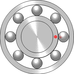
Image 1: This animation shows the rolling balls in a Conrad bearing. The cage and edges of the races are removed for clarity. Image by Plusminus taken from Wikipedia's ball bearing page.
These days bike bearings are used predominantly in the form of standard cartridge bearings. Some older bikes use a 'cup and cone' set-up where 'easy' adjustment means that the hubs can be made with slack tolerances in some dimensions that are subsequently adjusted to fit when assembled. There is a historical article here about the perceived pros and cons of cup and cone versus cartridge bearings.
These days the switch to to cartridge bearings is almost complete, which neatly illustrates which way the argument has gone.
To give it its full title, the following bearing is called a "Single row deep groove ball bearing."

Image 2: A single-row deep groove bearing or Conrad bearing showing the inside; balls and cage (left) and the full assembly (right) including balls, cage and grease all hiding behind rubber seals.
Before Conrad, ball bearings were made with a fuller complement of balls. Full complement bearings are also known as Max bearings.
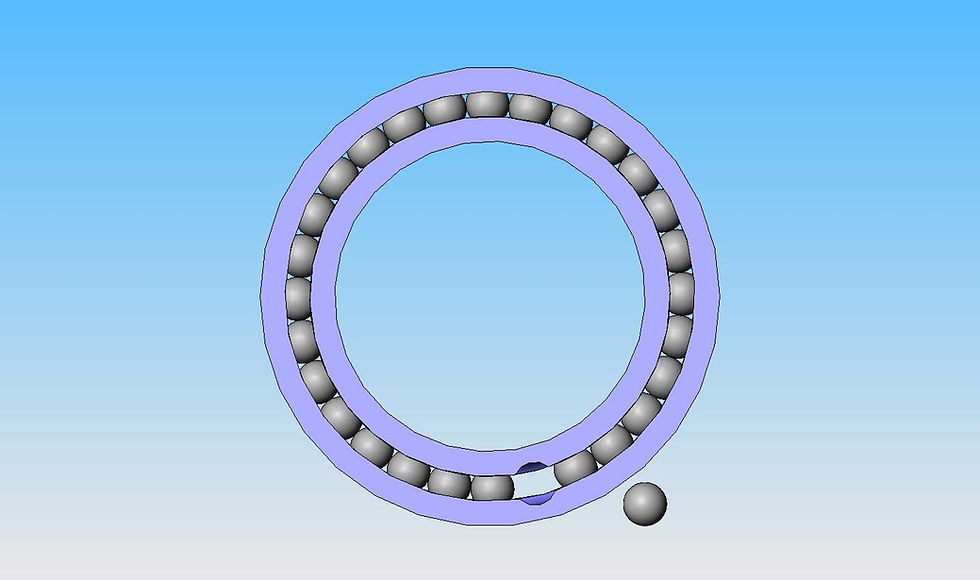
Image 3. In the image above the notches, through which the last bearing ball is inserted, are clearly visible.
If a full or maximum complement of balls is used (often called a max bearing) then the bearing can't be assembled unless a suitable slot is made in the side of the races into which the final balls can be inserted. These slots are cut into one side of the race grooves. When in use the slot presents a flaw in the bearing assembly which is especially detrimental when axial loading pushes the bearing balls over the slot. (Max bearings are generally used in higher load applications where the loads are radial. The higher loads are spread between more bearing balls.)
It was Robert Conrad who in 1903 first patented his way of assembling a bearing with 'perfect' races by using fewer than the full complement of balls and then holding those balls securely and evenly spaced out around by the use of a separate 'cage' component.
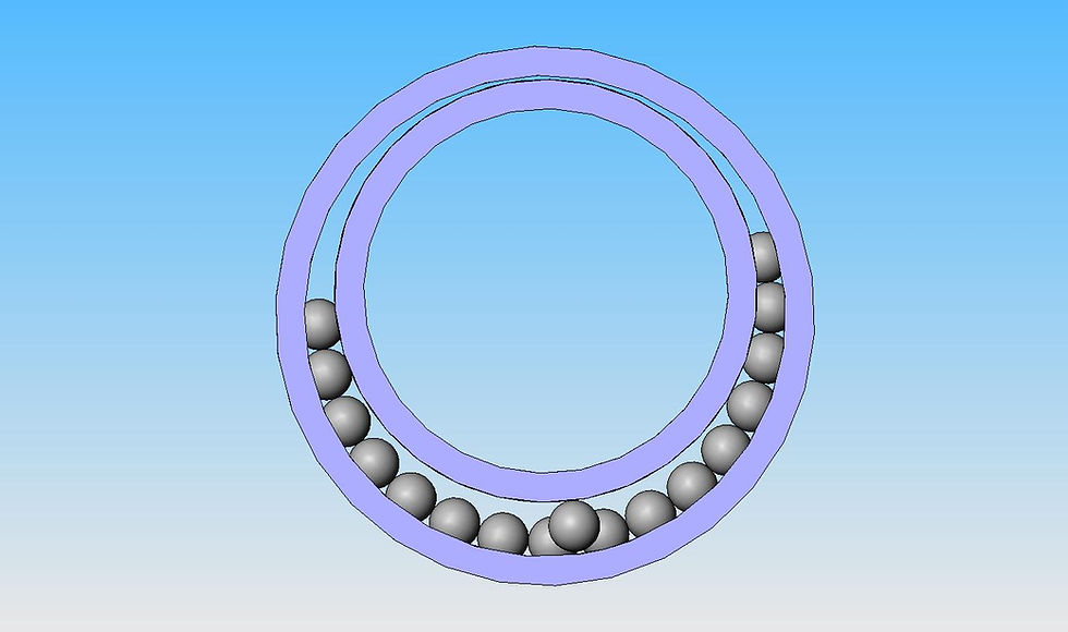
Image 4: With the bearing races held off centre it is possible to insert a reduced number of balls into the space created on one side.
Conrad's idea was to put fewer balls within the races so that the whole ball bearing could be assembled without having to cut notches in the side of the race grooves.

Image 5: Once the bearing balls are in place they are spaced out. A 'cage' (shown in red in the image above) then holds the bearing balls equally spaced around the circumference. The evenly spaced balls then hold the two races concentrically but allow them to move relative to one another in rotation. The races roll on the balls giving very low coefficients of friction.
Let's zoom into a cross-section of a ball in its two races. Each race is formed as a ring with a round section groove in which the balls rest. The groove is usually sized so the ball is a slightly loose fit in the groove. Thus, in principle, when loaded the ball contacts each race at a single point.
Image 6: When loaded, in theory, the balls touch the races at single points. This is due to the groove in the race being larger than the bearing's ball diameter.
Internal clearance
When bearings are not loaded at all for example before fitting into the hub they have what is called internal clearance.

A cross-section of the ball in its races. Note the very small gap around the ball which is normal when the bearing is carrying no load. This gap is referred to as 'internal clearance.'
Radial internal clearance is defined as the distance through which one ring can move relative to the other in the radial direction before the components touch. (In the image above, imagine the outer race is fixed and the inner race if first moved down until it stops and then up until it stops. The distance moved is defined as the 'radial internal clearance' of the bearing. Axial internal clearance is usually greater than radial clearance.)
When fitted in tight housings the bearing races are squeezed slightly reducing internal clearance to a new dimension called in-situ internal clearance. Bearings generally work best and last longest when this in-situ internal clearance is close to zero. However, if in-situ internal clearance is reduced by more than a tiny amount below zero the bearings quickly start to feel horrible, perform poorly and wear quickly. This is because the bearing balls are gripped just too tightly, with in this case a radial pre-load, before carrying any useful load.
Bearing Alignment
A deep groove ball bearing works best when it has very little pre-load and is perfectly aligned. Even a small misalignment adversely impacts performance.
The bearing below is correctly aligned.

The bearing above has its inner and outer races fully aligned. That is they are concentric and their outer faces parallel. The bearing is correctly aligned.
If bearings are held out of alignment during the assembly of housings and shafts, the resulting pre-loads can be very high when the assembly is bolted down tight. These pre-loads can easily exceed the bearing design maximum loads before any useful load is carried.

The bearing above is angularly misaligned. The inner and outer races (axes) are at an angle to one another.
For deep groove ball bearings, any misalignment must be kept really small to avoid massively accelerated bearing wear and increased friction.
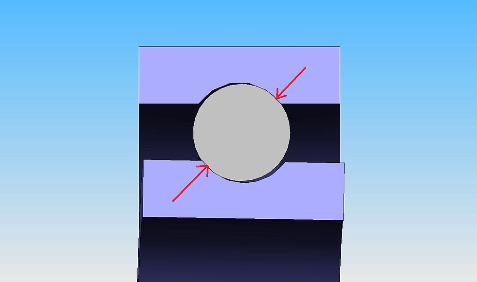
This image shows how the balls are squashed by angular misalignment causing high loads, extra drag and accelerated wear.
Bearings need to be correctly aligned
In order to operate efficiently bearings need to be correctly aligned. That is having their inner and outer races both concentric, parallel to one another and with suitable internal clearance. These are all prerequisites for longer life and low friction performance of bearing. If bearings are out of alignment by even a small angle, their life is dramatically reduced. This is well known amongst bearing experts. The experimentally measured increase in wear due to bearing angular misalignment is illustrated in the graph below:

This graph, from NSK, shows the importance of correctly aligned bearings.
The graph above is published by NSK but there are similar graphs published by other bearing manufacturers. To understand the graph, bearing life (on the vertical Y-Axis) is shown as 1 (Full life) with perfect alignment (when misalignment is zero). As angular misalignment increases along the X axis bearing life reduces gradually at first but suddenly drops very rapidly when misalignment exceeds a small angle. The lowest line represents a loss of 85% of bearing life at a misalignment angle of just 0.007 radians. What this graph does not show is the corresponding dramatic increase in friction.
Angular is not the only type of bearing misalignment possible. Another common problem in bike hubs is axial misalignment.
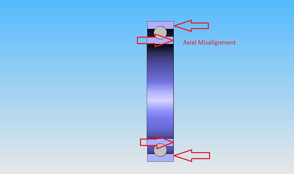
In the image above the inner and outer races are concentric but they are axially misaligned. The inner race is positioned slightly off-centre to the left in the image above.
Of course, combinations of misalignment are also possible adding further to the problems of extra drag and wear. The point is that the misalignment can add massive loads on the bearing balls and races before the design load (rider's weight) is even applied.
KOM have an advantage
The designers at KOM had the advantage of being able to start from engineering first principles. Thus their design ensures that the bearings are correctly aligned before you start riding. The Xeno hubs are even designed, front and rear, so that they can automatically adjust to different amounts of axle compression (axial pre-loading) depending on how tight you put your wheels back in your frame. How KOM's Xeno hub achieves this will be illustrated in another blog.
Static and Dynamic Loading
The explanation of various forms of bearing misalignment above considers static loading. That is the loads applied to the bearings before you start riding in the real world. Once you start pedalling, even on a smooth surface, the loads on the rear hub start to oscillate in time with your pedal strokes. Add in turns, bumps in the roads, rocks, roots, jumps and landings you can imagine the the loads in the axles and bearings are anything but static.
Dynamic Design
When riding the loads in a bike wheel are dynamic. That is often changing many times a second. The hub and bearings need to be able to remain correctly aligned when riding with these loads. Unfortunately, this is one of the major shortcomings of the legacy hub which almost always features a rear hub with a thin axle loaded almost entirely at its centre. This axle is prone to bending further when loads increase moving bearings and seals out of alignment. This can be described as dynamic bearing misalignment. It, of course, leads to extra friction and reduced bearing life.
KOM's solutions to bendy axles are explained in another blog which can be found here: Bendy Axles and Bearing Alignment


Comments